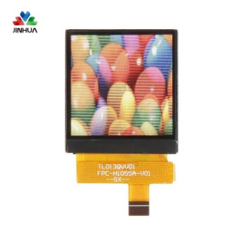
TFT LCD touch displays are becoming increasingly popular in devices ranging from consumer electronics to industrial and medical equipment. Although the design concept of using TFT touch displays is very mature, engineering and product design teams often encounter problems that are difficult to solve. Following best practices for TFT LCD touch screen use can save you a lot of troublesome situations.
Best Practices for TFT LCD Touch Screen Installation
Make sure there is enough space between the product case and the TFT LCD screen.
When installing the TFT LCD module, make sure it does not twist, deform, or bend.
CTP installation with bezel
The window of the frame should be larger than the active area of the capacitive touch panel (>0.5mm).
An insulating gasket (0.5~1mm) should be installed between the frame and the CTP surface.
For ultra-thin TFT LCD monitors, it is recommended to install a back bracket.
CTP surface mount
Double-sided tape is used to stick the settlement area of the TFT LCD display.
It is recommended to leave a gap (>0.3mm) between the product housing and the LCD cover lens.
When required (such as a TFT touch screen with no build-up structure), a back support with spacers should be used.
If additional cover lenses are required, engineers should recheck the CTP specifications for acceptable materials and thicknesses.
A gap of 0.2~0.3mm is required between the cover plate and the TFT LCD surface.
The window of the cover lens should be larger than the active area of the TFT touch screen (>0.5mm).
RTP installation
A gap of 0.2~0.3mm is required between the frame and the TFT LCD touch screen surface.
The frame should cover at least 0.5mm (B) of the visible area of the TFT LCD screen to prevent users from pressing the RTP ITO film connection area.
There should be a gap of 0.2~0.3mm between the side wall of the frame and the side wall of the TFT LCD.
Best Practices for Grounding Design
If best practices are not followed for grounding devices equipped with TFT touch displays, various problems can arise. Common challenges related to grounding:
The anti-noise ability is poor, and interference will have a negative impact on the operation of the equipment.
Long-term drift, or changes in voltage over time, can degrade a display's performance.
There are two key considerations: keep ground connections as short as possible, and keep impedance to a minimum. This requirement is particularly critical in the ground connection between the display housing and the touch controller. The diameter of the ground connection also has an impact, although it is not as significant as the length.
Another important consideration in grounding design is to avoid ground loops. Any floating conductive parts close to the touch sensor will cause instability in the touch function. So they should all have the same ground potential as the touch controller.


 English
 Deutsch
 русский
 español
 العربية


 IPv6 network supported
